le
PARAGLIDER DESIGN HANDBOOK
CHAPTER 7. DIAGONAL RIB TECHNOLOGY

7.1 Introduction

The 
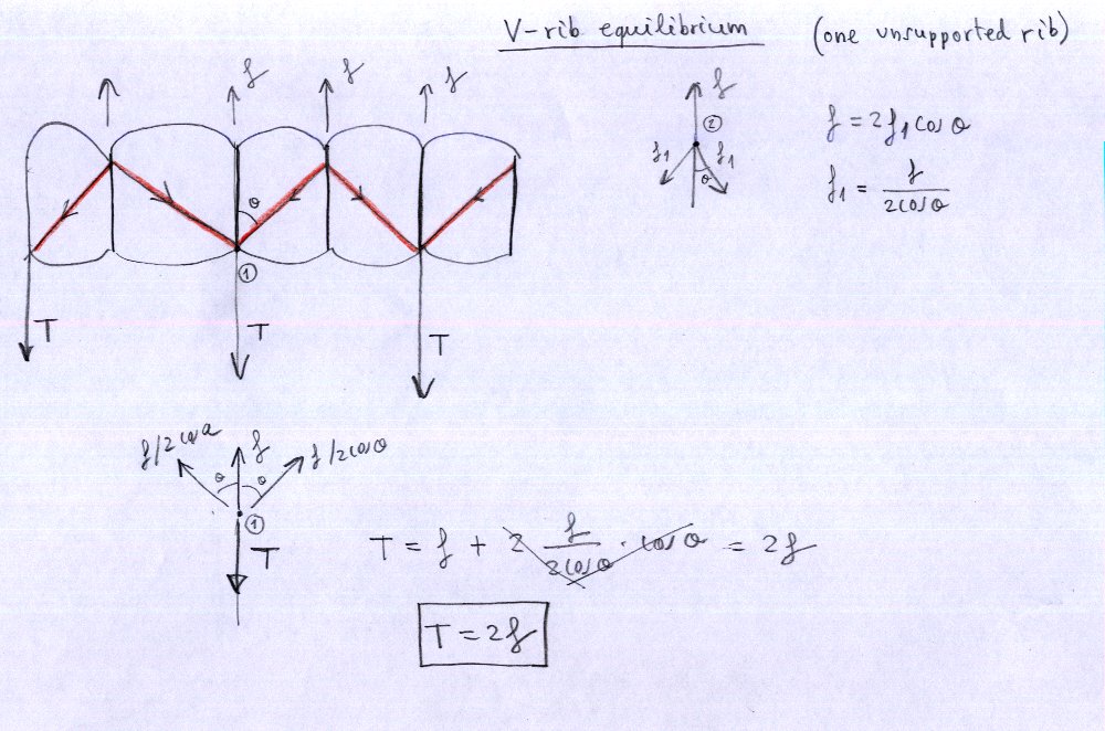
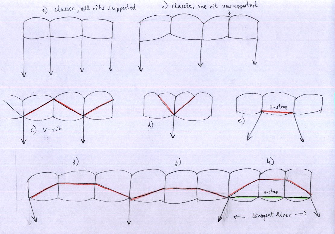
diagonal ribs (V-rib) are used primarily to reduce the number of anchors in the sail, thus reducing aerodynamic drag and therefore increasing the performance of the wing. The diagonal ribs are formed by complete ribs or partial (only in the vicinity of the anchor points), joining the intrados surface with the extrados surface of adjacent ribs.In 
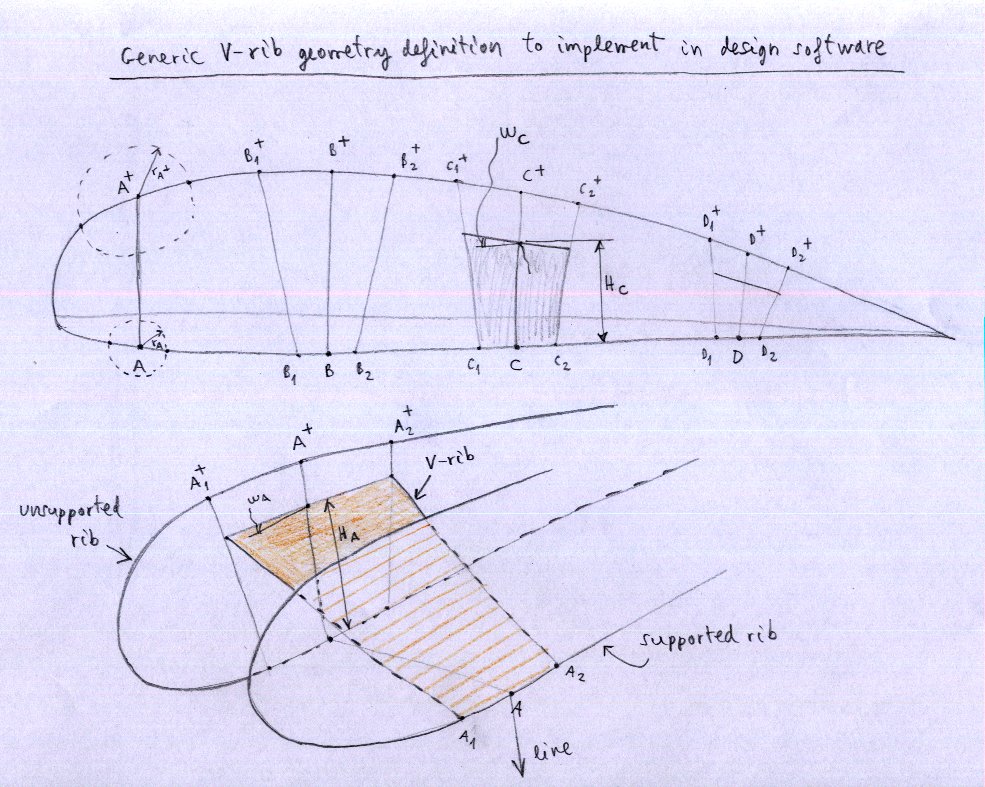
the case of partial ribs, it is common practice to link the top of the "V" in a segment of the vertical rib, near the top surface. We get the same effect and simplifies the construction and reduces weight. The evolution between a full diagonal rib and partial diagonal rib is understandable because of the need to leave ventilation holes in the diagonal ribs.

Flat straps (H-rib) , have another mission. They serve primarily to obsorb the tractions generated by divergent lines or ribs. Its use is advisable even in designs that do not include diagonal ribs, and where there are lines that can generate traction in the intrados panels. All paragliders designed by the laboratory include these horizontal bands (except gnuEASY design which has no divergent suspension lines, all converging).

To draw the shape from flat fabric panels that make up the diagonal ribs or flat straps, can be used the same mathematical method used to obtain the intrados or extrados panels placed between two ribs, detailed in Chapter 5. Development of flat panels.

Next, we include a series of figures that show how to work the diagonal ribs and flat straps.

7.2 Index of figures:

Fig 1. H-ribs (H-straps) equilibrium
Fig 2. V-rib equilibrium, one unsupported rib
Fig 3. V-rib equilibrium, two unsupported rib
Fig 4. Experimental correction insertions on the unsupported ribs
Fig 5. Experimental correction insertions on the unsupported ribs (3D view)
Fig 6. Generic V-rib geometric definition to implement in design software leparagliding
Fig 7. Various types of V and H ribs

H-rib
Fig 1. H-ribs (H-straps) equilibrium.

V-rib
Fig 2. V-rib equilibrium, one unsupported rib

V-rib 1 unsupported
Fig 3. V-rib equilibrium, two unsupported rib

Experimental insertion
Fig 4. Experimental correction insertions on the unsupported ribs

Experimental insertion 2u
Fig 5. Experimental correction insertions on the unsupported ribs (3D view)

V-rib geometric definition
Fig 6. Generic V-rib geometric definition to implement in design software leparagliding

V-H
 Fig 7. Various types of V and H ribs

index