
Lep Studio test on gnuA7 (24 m²)
Summary of the test runs and the calage methods on a built wing (LEP Studio Playground, fork studio-gnua7)
A report for the LEparagliding open-source community - Francois de Villiers - 29 October 2026
Summary
In the Playground the flexible gnuA7 wing flies about 3.9 calage points (chord percentage) further aft than the position LEP calculates. The offset was the same at every design position tried (3.92 to 4.03 points). It equals about 1 degree of wing pitch against the lines. There are two ways to remove it. Method A keeps Section 8 at LEP's converged values and shortens the A and B risers. Method B moves the carabiners forward in Section 8 by the same 3.9 points, as in the published layout, and leaves the risers at zero.
Both methods reach the same calage, but the wing does not fly the same. At 33 % the riser version flies at 9.79 m/s and 8.29 degrees with 55 % of the line load on the A row, and the layout version at 9.63 m/s and 8.60 degrees with 53 %. To land on LEP's solved calage of 37.13 % the design calage must be 33.23 % (B2, flown at 37.13 %). To fly at 33 % it must be 29.10 % (B3, flown at 33.04 %).
At LEP's solved calage of 37.13 % the flexible wing flies at 9.5 to 9.9 degrees, not the 8.5 degrees assumed in Section 35, and at 9.1 to 9.3 m/s against 9.49 m/s. Near 33 % the angle is 8.3 to 8.6 degrees. The A row carries 51 to 55 % of the load against 35 % in LEP, and L/D is 6.0 to 6.2 against 6.5. With the load recomputed on the deformed wing (fluid-structure interaction, FSI, rows 4 and 5 of the table) the speed rises to 10.3 and 10.9 m/s, the angle falls to 7.9 and 6.8 degrees, L/D rises to 7.2 and 6.9, and the calage stays within 0.2 point of the earlier value.
The wing as built
Setup: the runs in this document use the 4-riser line set (rows A to D), which gives excellent ground control. A 3-riser version of the line set exists and will be analysed soon.
Source: the gnuA7 project page and the published design file for the 24 m² size (version 2024-10-21). https://www.laboratoridenvol.com/projects/gnuA7/gnu-A7.en.html
Parameter | Value | Source |
|---|---|---|
Size | S-M, 24 m² flat area | Project page |
Flat span, flat aspect ratio | 10.16 m, 4.30 | Project page |
Mean chord | 2.36 m (24 / 10.16); centre rib chord 2.913 m | Calculated; LEP |
Cells | 33, with the last 2.5 cells on each side closed | Project page |
Weight range | 60 to 85 kg; tested with 80 kg pilot and harness, pilot centre 0.2 m below the carabiners | Project page; Section 35 |
Risers and lines | 4 risers (A to D), line configuration 4-5-4-3, 315 m of line in total, riser length 47 cm | Project page; Section 8 |
Airfoil | gnua, 18 % thickness, 140 points | Project page |
Structure | Diagonal ribs, V-ribs, H-straps, rod pockets (32 rods in the model) | Project page; mesh |
Upper skin | Ripstop, 40 g/m² | Project page |
Lower skin | Ripstop, 40 g/m² | Project page |
Ribs | Ripstop "hard", 40 g/m² | Project page |
Wing mass as built | Not stated on the project page. The fabric alone is about 3 kg (next row). | Project page |
Fabric mass in the Playground mesh at 40 g/m² | 3.07 kg for 76.8 m² of modelled fabric | Calculated from the mesh |
Wing mass used by LEP | 4.0 kg (Section 35, Mw) | Published file |
Lines and risers mass | 0.492 kg | LEP output |
Design values in the published file, which are starting estimates and not solved results:
- Section 8: glide ratio 7.0, plumb point 32.9 % of chord, calage 33.0 % of chord. The project page states "initial calage set at 33 %".
- Section 35: estimated speed 10.5 m/s, estimated angle of attack 8.5 degrees, Cl 0.58638, Cd 0.03735, drag correction cde 1.1, centre of pressure Ycp 0.850 m and Zcp 0.345 m, pilot area 0.438 m² with Cd 0.8.
- The 26 m² three-riser kit on the project page carries exactly the same Section 8 and 35 values, so they are template values and were not iterated for each size.
What is in Studio (apart from slight diff wing mass and cg)
Item | In the model |
|---|---|
Wing mesh | Version 5 with V-rib holes: 32,648 nodes, 37,100 skin triangles, 12,438 rib triangles, 71 straps (10 diagonal, 30 cross membranes, 31 mini-ribs), 164 lines (both halves), closed tip seam with hem, 32 rod pockets (not checked whether they act). |
Fabric area in the mesh | Top skin 28.5 m², vent 1.2 m², bottom skin 22.7 m², ribs 16.4 m²: 68.8 m² in total. |
Fabric density | Global value in the Studio profile 48.9 g/m², which gives a live wing mass of 3.755 kg. The headless runs fit the density to LEP's 4.0 kg (52.1 g/m²). The project page gives 40 g/m² everywhere. The Playground can override the density for each material (top skin, bottom skin, vent, rib web, rib patch, diagonal straps, cross straps, mini-ribs). A density override is set in the Studio session; its values were not recorded. |
Centre of gravity of the wing | Playground: 1.439 m behind the nose (49 % of the centre chord) and 0.514 m below the chord line at rest; live 1.426 m and 0.488 m. LEP: 1.208 m and 0.643 m (the default rule of 36 % of every chord). The difference is worth about 0.4 calage point (estimate). |
Aerodynamic loads | Flow5 table "b2" (ballooned skin), cell pressures, valid from 3 to 15 degrees. Force and pitch correction off. The chord position of each face is interpolated between the two ribs that bound it. Section 35 was filled with Flow5 values read at 8.5 degrees: Cl 0.7101, Cd 0.05925, Ycp 0.8465 m. |
Internal pressure | Equal to the dynamic pressure q in all 33 cells (about 56 Pa), mouths open. There is no control for it. |
Skin and ribs | Orthotropic membrane. Mouth strap with 4 layers. Detailed rib model off, so ribs are coarse webs and show no stress in the colour map. |
Lines and pilot | Elastic lines in rows A to D, auto riser trim with the A:B:C:D pull ratio 100:57:0:0. Pilot and harness 80 kg as a point mass; line and pilot drag from the Section 35 constants. |
Solver | XPBD, 30 substeps with 2 iterations, free flight with heading hold, damping 5 per second in the report runs. Final equilibrium in Studio with Newton static. |
Models
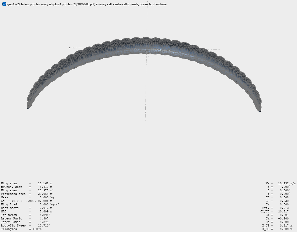
Figure 1. Flow5 billow model (every rib plus 4 profiles in every cell): 40,076 triangles. Span 10.162 m, area 23.977 m², root chord 2.912 m.
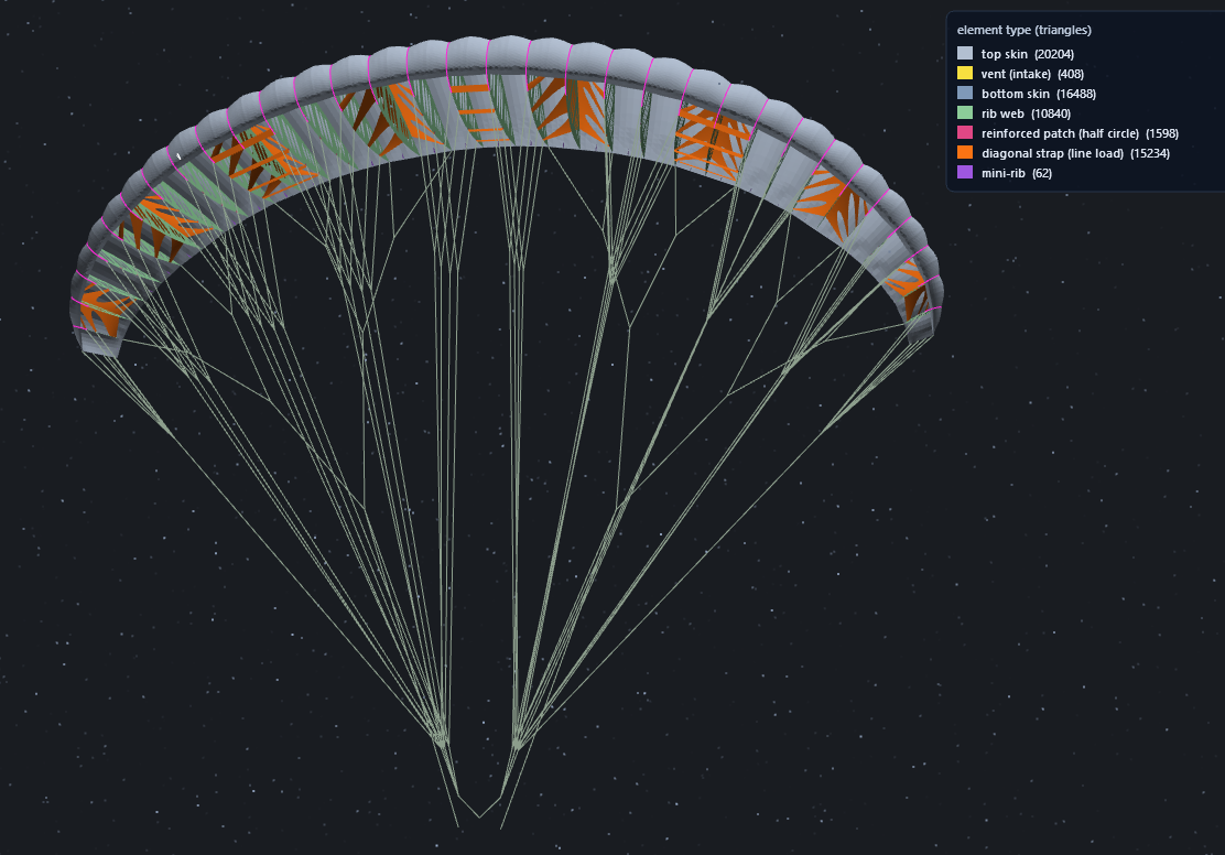
Figure 2. Playground mesh with the bottom skin hidden: 32,648 nodes. Triangles by element type: top skin 20,204, bottom skin 16,488, vent 408, rib web 10,840, reinforcement patch 1,598, diagonal strap 15,234, mini-rib 62.
Why the calage is so sensitive
K is the position of the main carabiners along the centre chord, in percent of the chord from the nose. It’s a line perpendicular to the chord. The carabiners hang 6.6 m below the chord. If the wing pitches by 1 degree against the lines, the point where the carabiners sit on the chord moves by 6.6 m × tan(1°) = 0.115 m, which is 3.95 % of the 2.913 m chord. So 1 degree of pitch equals 3.95 calage points, and 1 calage point equals about 0.25 degrees.
The measured offset of 3.9 points is therefore about 1 degree of pitch. A small deformation of the canopy under line load, a few centimetres at the trailing edge, is enough. This is why the published layout normally places the calage forward of the value LEP calculates and it’s more a decision by the designer than an exact calculation . In the Playground, 1 calage point took 7.6 mm of A riser (30.8 mm of A and 17.6 mm of B to move the wing by 4.03 points from its settle position to the intended calage).
Methods applied and results (Flexible wing - no fsi)
Riser change is the shortening of the riser in millimetres. The GR, plumb and calage columns are the Section 8 values. Think of the plumpoint as the point on the chord vertically up from the pilot while flying. Plumb point is a result of analysis but GR and collage determine the glider and line setup. The A row share is the share of the riser load carried by the A row.
Case | GR | Plumb % | Calage % | Riser change A / B | Settles at K | V m/s | Alpha deg | A row share |
|---|---|---|---|---|---|---|---|---|
1. As built, no riser control | 7.0 | 32.9 | 33.0 | 0 / 0 | 36.92 | 9.14 | 9.80 | 52 % |
2. As built, flown faster with the risers moved to 33 % | 7.0 | 32.9 | 33.0 | A shortened 30.3 mm, B 17.3 mm | 32.99 | 9.79 | 8.29 | 55 % |
3. LEP iterated, GR 6.5, no riser control | 6.497 | 38.15 | 37.13 | 0 / 0 | 41.16 | 8.64 | 11.22 | 51 % |
4. Section 8 lowered, then settles (B2) - Same Calage than 1 but with new GR | 6.499 | 34.24 | 33.23 | 0 / 0 | 37.15 | 9.11 | 9.87 | 52 % |
5. Section 8 lowered further, then settles (B3) | 6.499 | 30.11 | 29.10 | 0 / 0 | 33.04 | 9.63 | 8.60 | 53 % |
All rows were flown headless for 15 seconds with the Flow5 table b2, an 80 kg pilot, the fabric fitted to 4.0 kg and damping 5. Values are the mean of the last 2 seconds. The riser moves in row 2 are the values the automatic trim settled at.
What the table shows:
- The calage offset is constant. Flexible flight lands 3.92 points aft of the as-built design, 4.03 aft of the LEP-iterated design, 3.92 aft of B2 and 3.94 aft of B3.
- The corrections worked. Moving the design calage to 33.23 gave 37.15 and moving it to 29.10 gave 33.04, with the risers at zero.
- The same calage does not mean the same flight. At 33 % the riser version (row 2) flies at 9.79 m/s and 8.29 degrees, the layout version (row 5) at 9.63 m/s and 8.60 degrees.
- Moving the risers puts more load on the A row: 55 % against 53 % for the layout version at the same calage. In every case the A row carries more than the 35 % specified.
Methods applied and results (Flexible wing - with FSI)
gnuA7: setting the calage
FSI (fluid-structure interaction) couples the air flow and the canopy structure: the aerodynamic load is recomputed on the deformed wing, and the wing then deforms again under that new load. The flown shape is exported, 34 sections (at 25 % and 75 % of each cell) are cut from it and run in Flow5 (viscous, 3 to 12 degrees), the cell pressures of that run replace the table, and the flight continues for 15 seconds. This is repeated until the shape changes by less than 0.5 mm rms between two cycles. Rows 4 and 5 of the table above were run this way. In each pair of lines below, the first is the flight of the table above with the Flow5 table of the design wing, and the second is the same wing after the FSI cycles.
Case | GR | Plumb % | Calage % | Riser change A / B | Settles at K | V m/s | Alpha deg | L/D | A row share |
|---|---|---|---|---|---|---|---|---|---|
4. Section 8 lowered (B2), table of the design wing, no FSI | 6.499 | 34.24 | 33.23 | 0 / 0 | 37.15 | 9.11 | 9.87 | 6.01 | 52 % |
4. Same wing, FSI, 3 cycles (shape change 0.40 mm rms) | 6.499 | 34.24 | 33.23 | 0 / 0 | 37.18 | 10.27 | 7.86 | 7.20 | 54 % |
5. Section 8 lowered further (B3), table of the design wing, no FSI | 6.499 | 30.11 | 29.10 | 0 / 0 | 33.04 | 9.63 | 8.60 | 5.96 | 53 % |
5. Same wing, FSI, 3 cycles (shape change 0.38 mm rms) | 6.499 | 30.11 | 29.10 | 0 / 0 | 33.21 | 10.89 | 6.79 | 6.93 | 55 % |
Values are the mean of the last 2 seconds of the flight. The FSI flights continue the previous flight with the new table and use the rib-incidence option (gain 1, zeroed at the start of the flight), which turns the pressure with the skin as the ribs tilt. The first flight of each pair does not use it, so the change between the two lines includes this option; the two effects were not separated.
- Speed rises and angle falls at the same lift (820 N). B2: 9.11 to 10.27 m/s and 9.87 to 7.86 degrees. B3: 9.63 to 10.89 m/s and 8.60 to 6.79 degrees. Drag falls from 136 N to 114 N (B2) and from 137 N to 118 N (B3), so L/D goes from 6.0 to 7.2 and from 6.0 to 6.9, against 6.5 in LEP.
- Part of the drag reduction is the removal of an inconsistency: a table computed on the design wing and applied to a skin that has tilted leans the force forward. An earlier gnuC2 loop gave the same Flow5 drag at equal lift for the design and the deformed wing (change of 0.35 N). The split between this effect and a real change in these runs was not measured.
- The A row share rises by about 2 points (52 to 54 % and 53 to 55 %) and stays above the 35 % specified.
- Convergence: the shape moves 13.8 mm rms (largest local move 31 mm) in the first cycle for B2 and 14.8 mm (41 mm) for B3, then 1.6 and 1.5 mm, then 0.40 and 0.38 mm, so 3 cycles were enough. Each cycle is one 15 second flight; sections are cut at 25 % and 75 % of each cell, the tip section uses the foil at 0.5 thickness, and the Flow5 table covers 3 to 12 degrees.
gnuC2 (3 liner):
https://www.laboratoridenvol.com/projects/gnuC2/gnuC2.en.html
The same ways of setting the calage were run on gnuC2 (GR 8.461) and added here for comparison. The design file already carries LEP's solved Section 8, so row 1 is the as-built wing. Rows 2 and 3 bring the calage to LEP's solved value of 47.77 %, with the risers and with Section 8 lowered by the measured slide.
Case | GR | Plumb % | Calage % | Riser change A / B | Settles at K | V m/s | Alpha deg | A row share |
|---|---|---|---|---|---|---|---|---|
1. As designed, no riser control | 8.461 | 40.88 | 47.77 | 0 / 0 | 53.85 | 9.46 | 9.09 | 57 % |
2. As built, risers moved to 47.77 | 8.461 | 40.88 | 47.77 | A shortened 33.6 mm, B 19.1 mm | 47.77 | 10.18 | 7.57 | 59 % |
3. Section 8 lowered by the slide, no risers | 8.461 | 34.79 | 41.68 | 0 / 0 | 47.95 | 10.11 | 7.71 | 58 % |
All rows were flown headless for 15 seconds with the corrected chord-position mapping, damping 5 and the gnuC2 Flow5 table. Values are the mean of the last 2 seconds.
- The slide is 6.1 points on the as-built wing and 6.3 on the lowered design, against about 3.9 on gnuA7.
- Lowering Section 8 by 6.09 points (to 41.68 %) landed at 47.95 %, within 0.2 point of the target. Pulling the risers needs 33.6 mm of A and 19.1 mm of B, about 5.5 mm of A per calage point.
- The chord-position correction changes gnuC2 very little. As built, the checker without it gives 9.49 m/s, 9.02 degrees and L/D 8.89, and with it 9.46 m/s, 9.09 degrees and L/D 8.81. The calage is the same (53.85 %).
- At the solved calage the wing flies at 10.18 m/s and 7.6 degrees with the risers, against 10.01 m/s and 8.0 degrees assumed in Section 35.
Nose tension - gnu7A
The nose does not look fully tensioned in the prototype photo (Figure 3). The Studio model shows indents in the nose during flight (Figure 4). Ground-handling studio mode has not been checked.
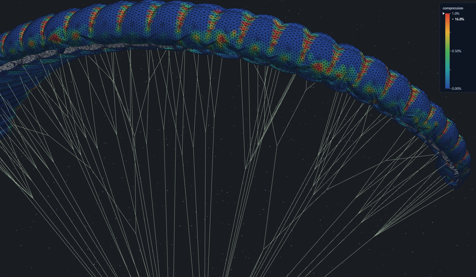
Compression 1 % showing nose indentation and typical cringle areas. (also visible in real built)
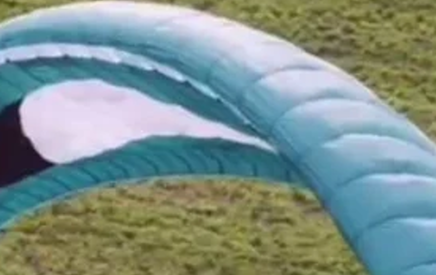
Figure 3. Nose and intake of the prototype (photo).
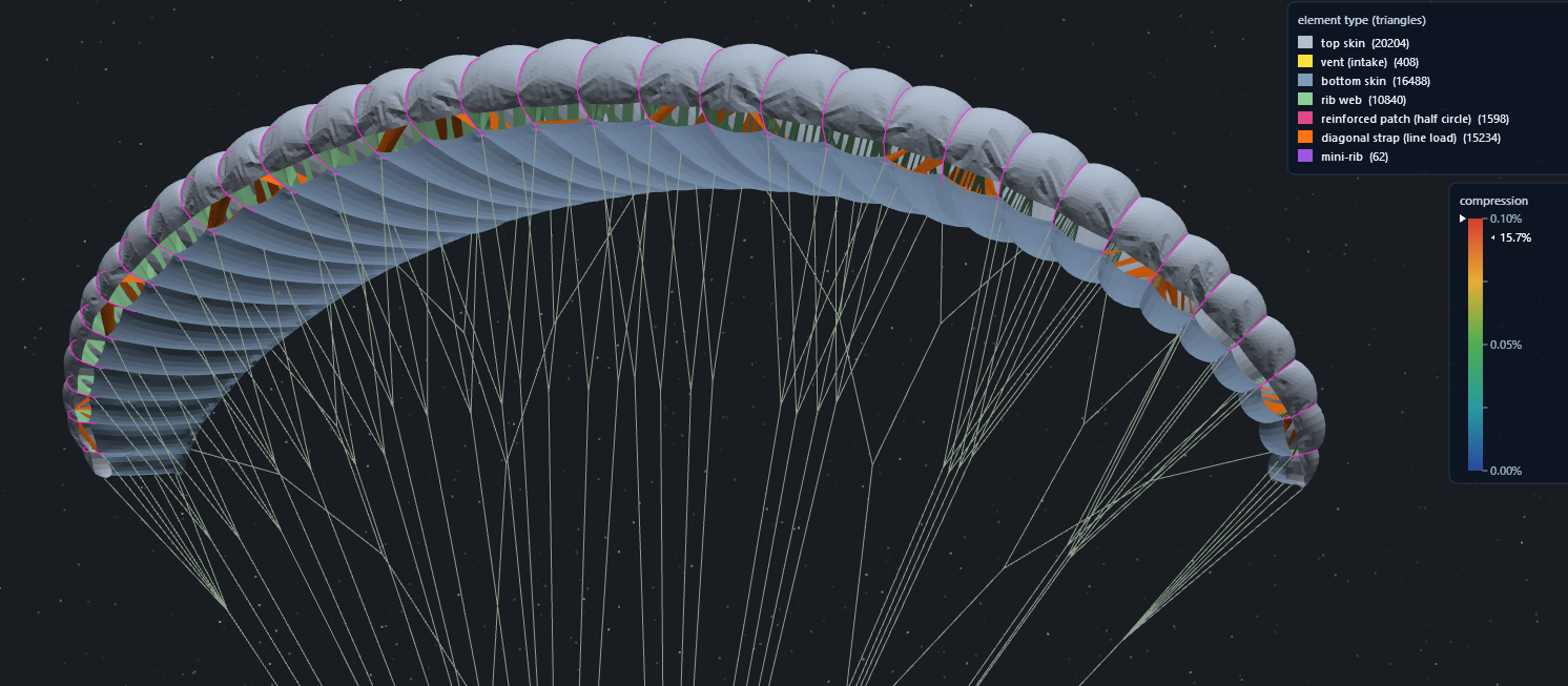
Figure 4. Studio Playground in flight mode: indents along the nose of the top skin.
Open points
- Wing mass and centre of gravity. The live mass of 3.755 kg corresponds to the global density of 48.9 g/m² and does not include the override. The fabric alone at 40 g/m² is 3.07 kg, about 0.9 kg less than LEP's 4.0 kg. What the missing mass is (rods, tapes, reinforcements) and where it sits would change the centre of gravity.
- Line load shares. The A row carries 51 to 55 % in every case against 35 % specified, so the cause is the Playground's line geometry or load model, not the method. The reason is that the glider flex and line settling overrides any load setup by shortening lines. This could now be improved.
- Three-riser kit. The published 26 m² kit (2-3-2 lines, about 12 % less line cross-section after scaling to 24 m²) changes only Section 9. A 24 m² version has not been analyzed.
- Nose. All 33 nose bays are slack and the A row carries half of the line load. The tests that would separate the causes (pressure at fixed risers, rods on and off, A-row share) have not been run.
- Check groundhandling tension.
Computing time
Typical times for one wing, measured on three ordinary PCs working in parallel (a 15 second flight is 900 frames).
Step | Time |
|---|---|
Mesh and engine export | About 1 min |
Flow5 pressure table, viscous run at 8 to 10 angles | 5 to 9 min |
One 15 second flight in the Playground (XPBD) - with damping this reduces to 8 min | 31 to 57 min, typically 40 min/20 min |
Static Newton or mem4py solve of the end frame - Newton static is the best | Newton 7 to 43 min, mem4py 9 to 44 min |
Report set: 10 flights (gnuA7 and gnuC2 cases) | 1 h 40 min on 3 PCs |
Calage sweep, one wing (gnuC2): 7 calage positions, flexible and rigid, 19 flights, 6 Newton and 6 mem4py solves | 4 h 50 min on 3 PCs (16 h of computing) |
FSI, one wing, 3 cycles (gnuA7): each cycle is 5 min of Flow5 and a 35 to 39 min flight | 1 h 30 min to 2 h 10 min per wing, 2 PCs in parallel |
FSI with a Newton and a mem4py solve after every cycle (gnuC2, 3 cycles) | About 5 h on 2 PCs |
The three PCs are an i7-9750H (6 cores), a Ryzen 7 3750H (4 cores) and an i5-7200U (2 cores). The same jobs on one high-end workstation have not been timed, so the totals above are the wall clock of this shared set-up.
Conclusion
The Playground has become a scientific tool. Before any flight has taken place it already shows how the wing deforms, how the fabric is tensioned, what twist results and where the calage settles for trim. It identifies problem areas such as creases and nose indents, and it makes different design strategies easy to compare. For the designer it is an extra tool that gives a view into fabric deformation that was not available before, and it can be adapted to any concept, including the optimisation of harnesses.
What the tests on gnuA7 and gnuC2 showed:
- The flexible wing settles further aft than LEP calculates: about 3.9 calage points on gnuA7 and 6.1 to 6.3 on gnuC2. Shortening the risers or lowering Section 8 by the measured amount brought both wings within 0.2 point of the target.
- The two corrections give the same calage but not the same flight: speed, angle of attack and the share of load on the A row differ, so the choice between them is a design decision.
- Recomputing the load on the deformed wing (FSI) changes the flight. On gnuA7 the speed rises by about 1.2 m/s, the angle falls by about 2 degrees and L/D goes from 6.0 to about 7, while the calage does not move.
- Open points remain: the A row carries 51 to 59 % of the line load against 35 % in LEP, the nose is slack, and the wing mass and centre of gravity are not yet matched to the built wing.
The method needs a high-end computer and some time (see the computing time table above), but it is much cheaper to optimize on the computer than to build many variants of a wing. The next steps are to learn more about the exact deformation around the brakes and to analyse over all flight regimes and also expand it to single-skin gliders.