
PARAGLIDER DESIGN HANDBOOK
CHAPTER 3. MAIN LOBE
3.1 Main lobe "voute"
3.1 Influence of the shape of the lobe
3.3 Geometric torsion (washin)
3.4 Profil insertion
3.1 Main lobe or "voute"
The main lobe or voute is the front view of the canopy.
Previously, we
need to define a line of referral on the plane XY of the sail,
perpendicular to the central chord and at a distance "d" from the
leading edge. Usually, this distance is 1 / 2 to 2 / 3 of the chord of central profile, but can be defined any other. The reference line is on the same plane as all the chords of the wing, in their definition in plan.
Then, we define the main lobe, as the referral line curved in a vertical plane XZ
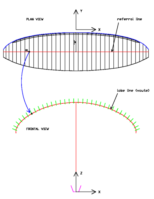
Fig 3.1 Line of referral and main lobe
The most common lobe forms are:
a - Circle of radius R and center O in the middle of the main carabiners
b - Two circles of radius R and centers at each of the left and right maillons
c - An ellipse of semiaxes a and b, being 2a the projected span and b the total sail arrow
d - Bionic profile type, with slightly sunken center and wing tips upturned
e - Any
symmetrically form, by modification of the above, and defined analytically by
a mathematical function z = f (x), or discreetly indicating a set of
coordinates (x, z)
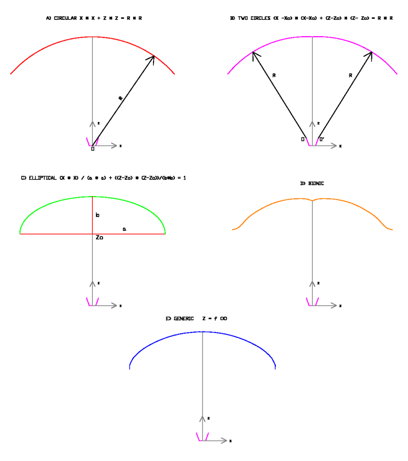
Fig 3.2 Most common lobes
3.2. Influence of the shape of the lobe
The shape of the lobe is of great importance in the behavior of the wing. Particularly in the sail tension.
The influence of the shape of the lobe should be studied locally (in the affected cells) and globally, across the wing.
In general, the greater curvature, means greater spanwise
tension, and less curved, less spanwise tension. The wings of large
curvature has been calling "high arc". This high arc is required to
maintain tension in high aspect ratio wings. However the high arc wings have lower projected area and create more drag, compared to flat wings. Then, designers should seek a compromise, and also playing with other parameters that influence the stability and performance.
The ideal forms are obtained through experience and analysis of other wings. In particular the study of frontal view photographs of other wings is of great interest for new proposals.
(...more)
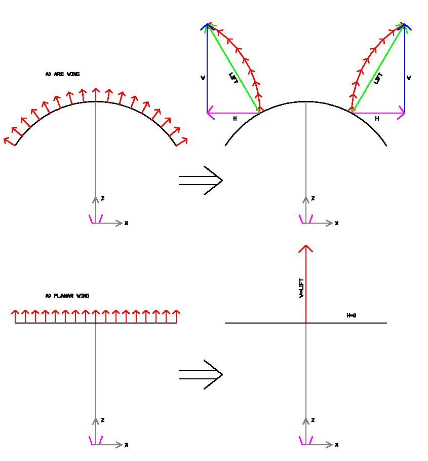
Fig 3.3
3.3 Geometric torsion (washout - whashin)
The
process of bending in space (in a vertical plane) the plan reference line, forms the entire 3D geometry of the wing if in that
process, we move and rotate simultaneously all the chords with their
profiles.
We
need to define at least the relative angles of incidence of the
profiles, and the inclination of the plane that contains them.
The relative
angles of incidence of the profiles (central profile considered at
angle 0 °) form the geometric torsion. In
the case of paragliders, torsion usually is positive "washin", while
the
profiles of the wing tips are at a greater angle relative to the
central. The washin promotes spanwise tension and stability, preventing
the wing tips fold unexpectedly. Hang gliders and rigid wings use
negative geometric torsion (washout), for other reasons.
The total value of washin depends on many factors. Usually, satisfactory results are obtained with values between 4 and 5 positive degrees. The
variation of the angle along the span may be proportional to the distance to
the center of the wing, or proportional to the chords, at criterium
of the designer.

Fig 3.4 Washin and washout
3.4 Profil insertion
The profiles form the 3D structure of the wing following the curvature of the main lobe, but first we must make two rotations:
1)
Rotation profile until its relative angle of incidence (alpha), and relative on a point of
his chord RP (which may or may not coincide with the point of the reference
line RL , a criterion).
2) Rotation of the plane of the profile, along the axis of the chord AB.
The
rotation angle in this step is the necessary to bring the plane of the
profile normal (90 °) to the curve of the main lobe, or another angle
defined by the designer.
For practical purposes, for each profile, at least the designer must define the following parameters:
Chord lenght: AB
Location of referral line: RL
Location of rotation point: RP
Relative angle of incidence: alpha
Angle of the profile plane: beta
Then, moving the reference point, until its corresponding point on the curve of the main lobe, we obtain the 3D wing
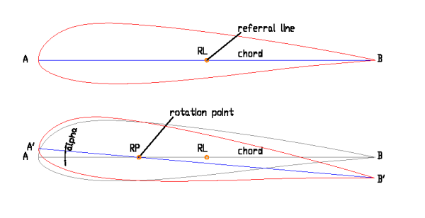
Fig 3.5 Rotation of the profile (alpha)
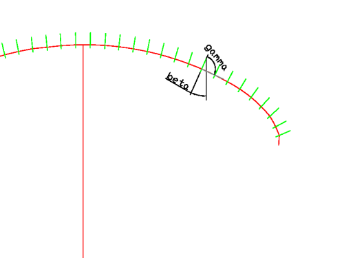
Fig 3.6 Rotation of the profile (beta)