
PARAGLIDER DESIGN HANDBOOK
CHAPTER 6. OVALIZATION
6.1.
Introduction
6.2
Analysis of the ovalization in
transverse direction to the cells
6.3
Analysis of the ovalization
along
the axis of the cells
6.4.
Corrections to the panels
6.1. Introduction
It is well known that the upper and lower surfaces of the cells are not
flat. Because the structure of the paraglider is textile, and that the
internal pressure is higher than outside, the cells tend to adapt a
cylindrical shape between ribs.
According to measurements made by the LE, at various paragliders, the
width of the cells in flight is around 5-6% less than the width of the
panels.
In this chapter we analyze the effect of this and its consequences on
the geometry of the panels.
6.2 Analysis of the
ovalization in
transverse direction to the cells
In the figure below shows the effect of a ovalization (billow) in a
cross-section to the cells.
The ribs remain flat due to equal pressure on both sides,
but the upper and lower panels adopt cylindrical shapes along them. The
degree of ovalization depends primarily on the wisespan tension.
Measurements made on various models show ovalization degrees around 6%
higher in the arco regarding the length of segment.
It is impossible to avoid ovalization and its interest lies in the need
to project the top and bottom panels adapted to it.
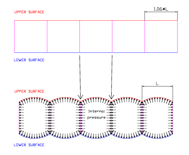
Fig 6.1: Ovalization in
transverse direction to the cells
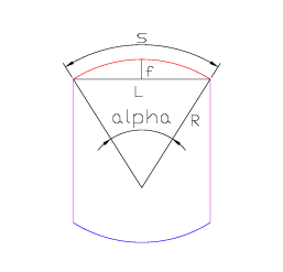
Geometry of the ovalization:
S = R * α
L = 2 * sin (α/2)
R = f + L * cos (α/2)
data: L, S
unknowns: R,f,α (solving the previous system of three equations)
Fig 6.2: Cell ovalization
6.3 Analysis of the ovalization along
the axis of the cells
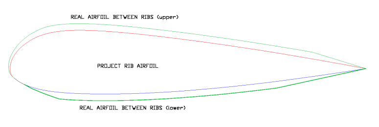
Fig 6.3: Ovalization along
the axis of the cells
The figure below shows the effect of
ovalization lengthwise. The main
consequence is that the "virtual" airfoils contained between two
textile ribs
are different and bigger (from 18% to 21.5% in the case drawn). This
only takes into account implicitly in the design of the wing, the study
focused on the "true" or project airfoils.
An important consequence of this analysis is that the contour length of
the virtual airfoils is greater than the length of real contours of the
projected airfoils. In the example airfoil, the difference in length is
about 2.26% in the upper surface and a 0.9% on the lower surface.
Differences in the lower surface are minor, but differences on the
upper surface, are higher because of the curvature of the leading edge.
At the area of the leading edge there are two independent curvatures,
one due to the ovalization efect and another due to the curvature of
the leading edge. The
resulting surface is not developed in a flat figure. Hence the solution
is to create a micro wrinkles in the area joining the top panel with
the rib to offset the differences in length.
Then two figures are attached with a cell in 3D for better
understanding of the above.
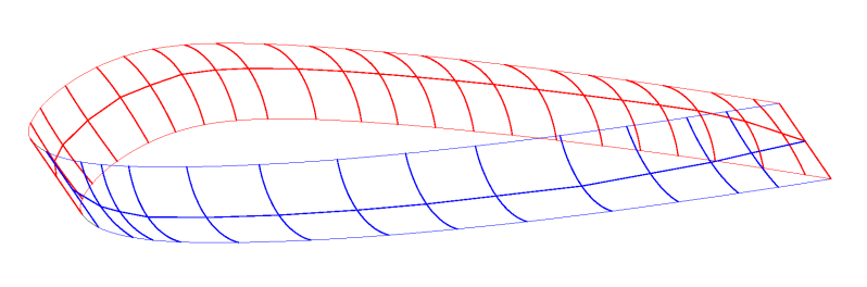
Fig 6.4: Cell ovalization
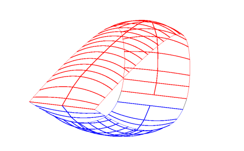
Fig 6.5: Cell ovalization
6.4. Corrections to
the panels
To take into account the effects of ovalization, corrections must be
made in panels obtained by the method describeb in the previos chapter.
We simpli need to increase the wide of the panels in a total of around
6% (3% on each side, and this value must be adapted in each paraglider
model).
Around the LE and TE is a linear transition of wide to reduce
ovalization and increase the sail tension in the area.
Normal values of transition points are as follows:
|
From LE
|
From TE
|
Upper panel
|
10%
|
15%
|
Lower panel
|
10%
|
25%
|
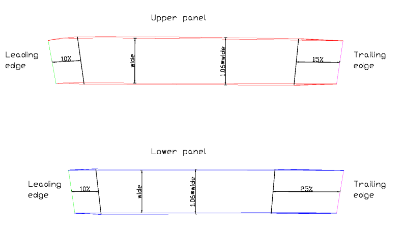
Fig. 6.6: Corrections to the panels.
index