By Francois De Villiers (Cape Town, South Africa).
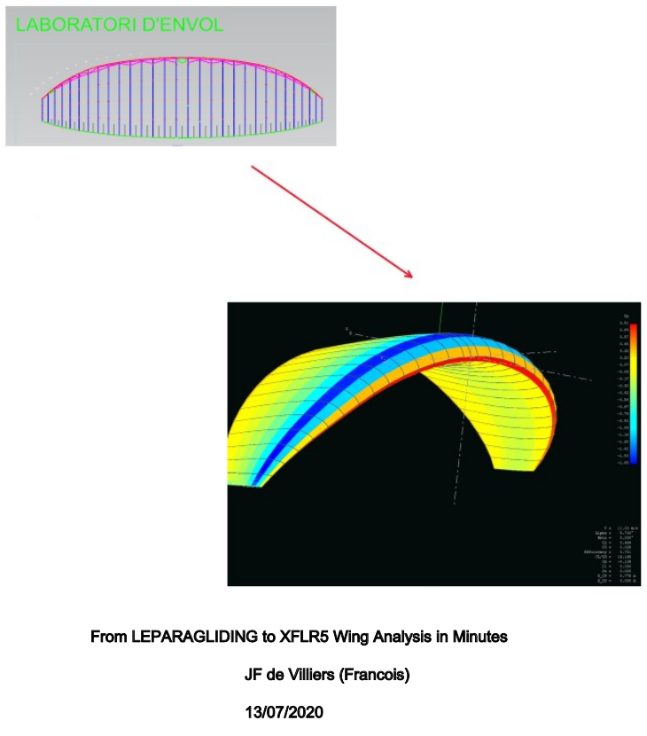
1. From LEparagliding to XFLR5 analysis in minutes
There are various ways to analyze the aerodynamic behavior of a wing
defined with LEparagliding (LEP) and the method described below is to
convert the data already available in LEP in an exact and very accurate
way for use in xflr5 wing analysis.
When it comes to wing analyses using the software xflr5 it is important
to understand the limitations of the various solving methods. Studying
the xflr5 guidelines pdf document downloadable from
https://sourceforge.net/projects/xflr5/files/
is a good starting point. The wing design and analysis
capabilities are based on the Lifting Line Theory, the Vortex Lattice
Method and the 3D Panel Method
It is important to note that LEP is a paraglider geometric layout
program, and that no aerodynamic calculations are performed inside the
program and needs to be done externally either with something like
computational fluid dynamic (CFD) software or as in this case xflr5.
LEP can export the 3-dimensional wing to STL format and methods exist
to convert this to surfaces/solids for use in conventional CFD software
but not described here. During the early stages of design, the
use of Xflr5 is a great tool to use in conjunction with LEP firstly to
define and understand the aerodynamic profiles used in LEP wing
definitions and then secondly to understand the wing and its
aerodynamic behavior. The final step is to use CFD and structural
finite element (FEM) software to study and optimize the paraglider
aerodynamic and structural behavior which includes the effect of the
inlets at the leading edge.
Continue reading here:
 Lep_to_xflr5 (v4).pdf
2. gnuA6 example:
Lep_to_xflr5 (v4).pdf
2. gnuA6 example:
leparagliding.txt
gnuA6.xfl stored polars
import_wing.xwimp geometry to import inside xflr5
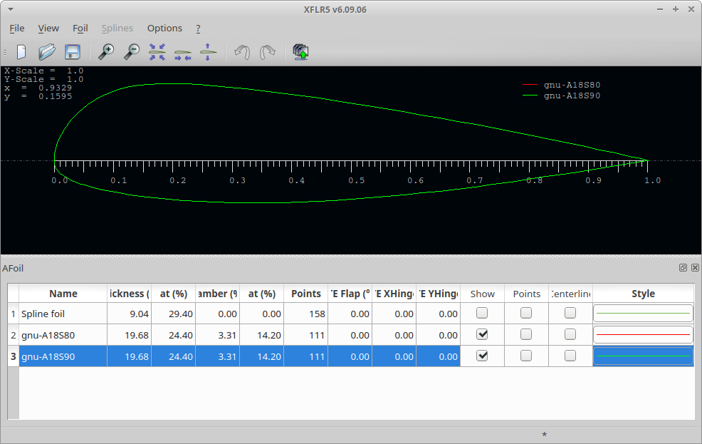
gnu-A18S90.dat gnu-A18S90.dat used airfoils (gnuA airfoil scaled to 90% and 80% used in gnuA6)
Step1: Direct foil design. Load all airfoils
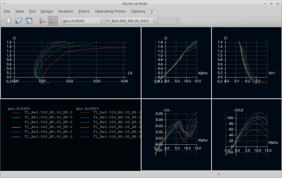
Step 2: Xfoil direct analysis. All foils in list. Adjust Reynolds and analysis range

Step 3: Batch analysis done
Step 4: Wing and plane design. Define a new wing. Import wing (
.xwimp)

Step 5: Wing imported

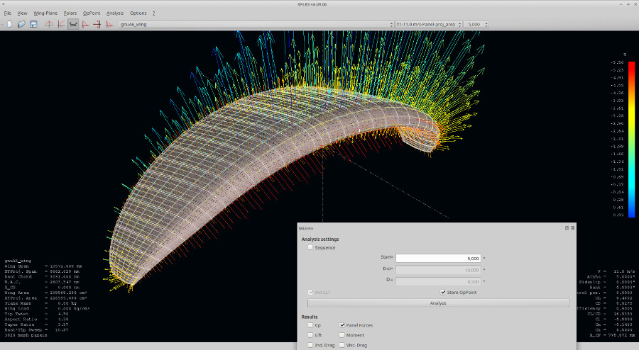
Step 6: Analysis definition. Speed 11 m/s, method 3D Panels
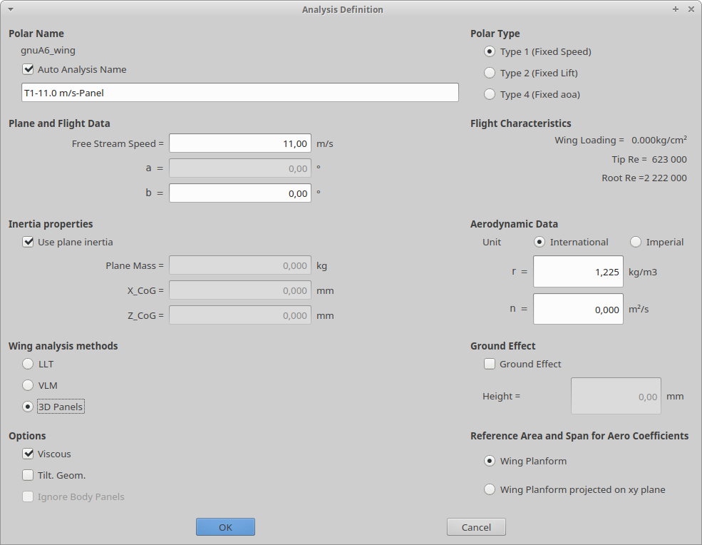
Step 7: Analysis settings

Step 8: Analyze, selected Cp, Stream

9. Analyze, selected panel forces
 3. Laboratori notes and future developments.
1) In order to be able to quickly use the analysis method presented
here by De Villiers, it is planned that in the next version of
LEparagliding a geometry file '
.xwimp'
will be automatically generated to import paraglider into XFLR5. Thus,
it will not be necessary to manually enter the geometric data from LEP
to XFLR5. Additional profiles representing billowing (cell curvatures)
will also be considered for a more realistic analysis.
2) De Villiers is currently studying how to model the full paraglider
with Xflr5, simulating the pilot with the tail and stabilizer, and the
lines drag by applying the proportional part of drag to the wing and
the pilot.
4. Full Hegala analysis
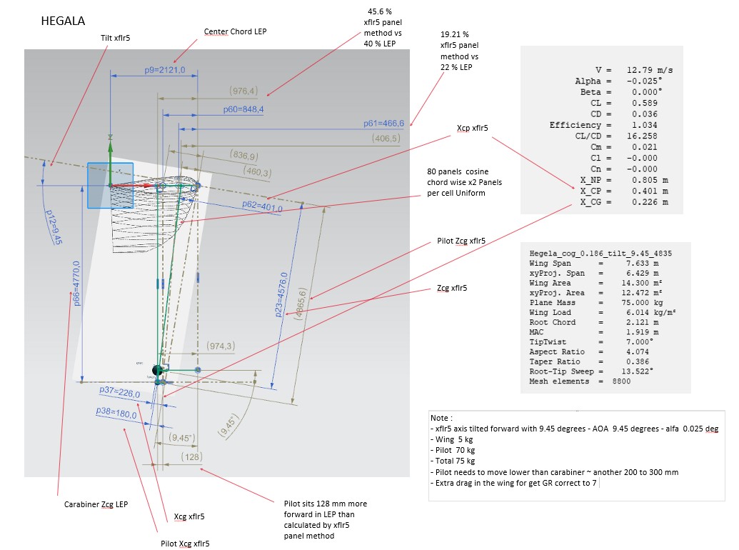
2022-07-23 Complete
Hegala analysis using LEP and XFLR5 by JF De Villiers