1. INTRODUCTION
2. CONTENTS AND REFERENCES OF THE /ta FOLDER
3. USING THE PROGRAM
4. PRINCIPLES OF THE SPEED AND GLIDE RATIO CALCULUS
5. DOWNLOAD
********************************************************************************
1. INTRODUCTION
********************************************************************************
This software developed by Laboratori d'Envol performs the analysis of a GPS ".gpx" file types. Using
the .gpx with wind data (speed and direction) existing at the time of
the flight, calculate the
average speed and
glide of the flight at zero wind (
glide ratio and speed of the wing).
The program was written mainly to
find the parameters of speed and
glide ratio of paragliders prototypes, and other gliding wings.
To determine experimentally the speed and glide angle of a new prototype, we only need make a few flights under zero wind conditions and the most straight way possible. This program helps to use tracks, made even on wind conditions and not straight paths, but that's always proferible.
Requirements to use this program are: a computer with GNU/Linux or other UNIX compliant. Software to be installed (via
apt-get, synaptic or equivalent)
bash
proj
Viking (optional but recommended)
The program
ta requires no
installation, since is running .sh file types and .out executables.
Simply unzip the "ta.zip" folder and all its contents in the working
directory chosen by the user.
*******************************************************************************
2. CONTENTS AND REFERENCES OF THE /ta FOLDER
********************************************************************************
The contents of the folder "/ta" is as follows:
/comp
/dxf
flight.txt
Manual.txt
data.gpx
ta.sh
"/comp" is the folder that stores source code, executable and
supporting files created during program execution, as well as data and
results. Normally you do not need to access this folder, except for
curiosity or study and modify the code.
"/dxf" is the folder where the two .dxf files are generated
automatically. "Longitudinal.dxf" with the developed longitudinal
profile of the flight (calculated with wind and without wind), and
another file "Track-3d.dxf", with a 3D polyline of flight in UTM
coordinates. Currently the generation of DXF files is not very
developed, but is not necessary for the program's objective. DXF's are
illustrative only. Use zoom_extens command.
"flight.txt" is an input data file describing the flight data and wind
exists. Contains eight lines that must be adapted to each flight
analyzed, with a contents like these:
1: "My flight zone"
2: "17-11-2012"
3: "Flight 1 of the day"
4: "Prototype 1 glider"
5: "Test pilot name"
6: 90.0
7: 10
8: -45
Lines 1 through 5 are descriptive and must be updated so obvious, always inserting the text between "".
Line 6 indicates the total weight in flight, expressed in Kg. Used only for reference.
Line 7 indicates the average wind speed during flight in km/h.
Line 8 indicates the wind direction in degrees measured clockwise with
respect to north, between the values [-180, 180]. For example, an
east wind will be expressed as -90, west wind by 90.
"Manual.txt" is the manual.
"data.gpx" is the .gpx file with track points. It must be a .gpx with a
single track, and a track sufficiently representative regarding what is
to be measured. It is preferable a straight track or just with slightly
change direction, and in an area where it is little variation in wind
speed and direction. For an usable .gpx, it may be necessary to extract
and trim the original GPS track with a program like Viking or similar.
Each point on the track in .gpx file must have a structure like this:
</trkpt>
<trkpt lat="41.508389000978106" lon="1.254308199887108">
<ele>1021.5380859000001</ele>
<time>2012-08-17T16:23:33Z</time>
"ta.sh" Is the shell script to be executed
*******************************************************************************
3. USING THE PROGRAM
*******************************************************************************
To use the program, simply follow these three steps:
1) Edit flight.txt according indicated above (details of the flight and wind).
2) Overwrite the data.gpx file with the track to be analyzed
3) Run the ta.sh script from a terminal located in the working directory ta:
. / ta.sh
Immediately the main results of the analysis appear in the terminal.
A more detailed result is saved in the new file Track_Analysis.txt, that appears in the working folder /ta.
And finally in the folder /dxf appear the files Longitudinal.dxf and Track-3d.dxf.
********************************************************************************
4. PRINCIPLES OF THE SPEED AND GLIDE RATIO CALCULUS
********************************************************************************
The .gpx file contains a list of points, arranged consecutively forming
the track. Each point contains the geographical coordinates (latitude and
longitude), altitude, and time instant in which the point is was taken.
To perform geometric calculations for distance and angles between
points, it is advisable transform the geographical coordinates of the track, to UTM
system, where longitude and latitude coordinates are transformed to X
and Y measurable in meters. In our case, we use the
proj program with the following command:
proj +proj=utm +ellps=GRS80 -r lalo.txt > xyutm.txt
Transforms (latitude, longitude) in auxiliar file lalo.txt, to (x,y) in UTM in file xyutm.txt, using GRS80 ellipsoid.
Adding elevation in meters and time in seconds, we get the file xyzt.txt that allows all calculations with ease.
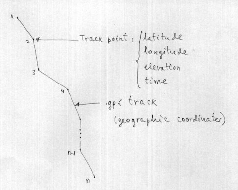
Figure 1. The .gpx track in geographical coordinates
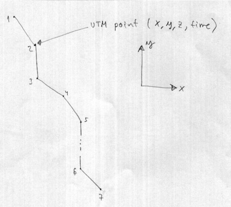
Figure 2. The track in UTM coordinates
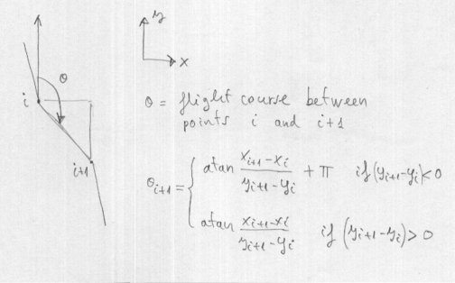
Figure 3.
One of the parameters imporant to determine from UTM coordinates, is the direction of flight, between the instant "i" and "i+1". It is easy, using the formula of the arctangent, taking special care to all casuistry and associated signs.
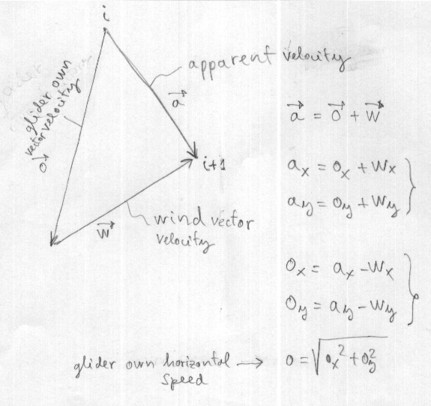
Figura 4.
Let us consider that the apparent velocity of the glider, is the vectorial sum of the wind velocity with the velocity of the wing itself. Subtracting vectorially, It follows the speed of the wing itself. In this calculation we will consider only the velocity components in a horizontal plane, assuming that the wind acts in a horizontal plane.
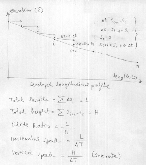
Figure 5.
Knowing the horizontal speed of the wing itself (and already compensated for the effects of existing wind), between two points on the track, you can find the distance no wind, just multiplying the speed by the time increment. The height difference between two instants, is simply subtracting altitudes. Then the glide ratio is simply the division between the distance traveled and the height difference. Or also, the division between the horizontal speed and vertical speed.
*******************************************************************************************
5. DOWNLOAD
*******************************************************************************************
Download
ta.zip folder (314 K) containing the program "track analysis"
/comp
/dxf
flight.txt
Manual.txt
data.gpx
ta.sh
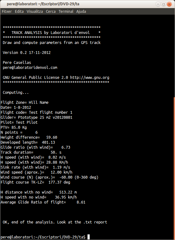
Figure 6. Track Analysis screenshot