PART 1: NOTES ON 3D FORMATION OF THE LEADING EDGE IN A PARAGLIDER, USING RIPSTOP FABRICo
PART 1: Notes on the 3D formation of the leading edge in a paraglider, using ripstop fabric.
PART 2: 3D-SHAPING PROGRAMMING ESTRATEGY
PART 3: Negative 3D-shaping
PART 4: A device for experimental study of deformations and wrinkles
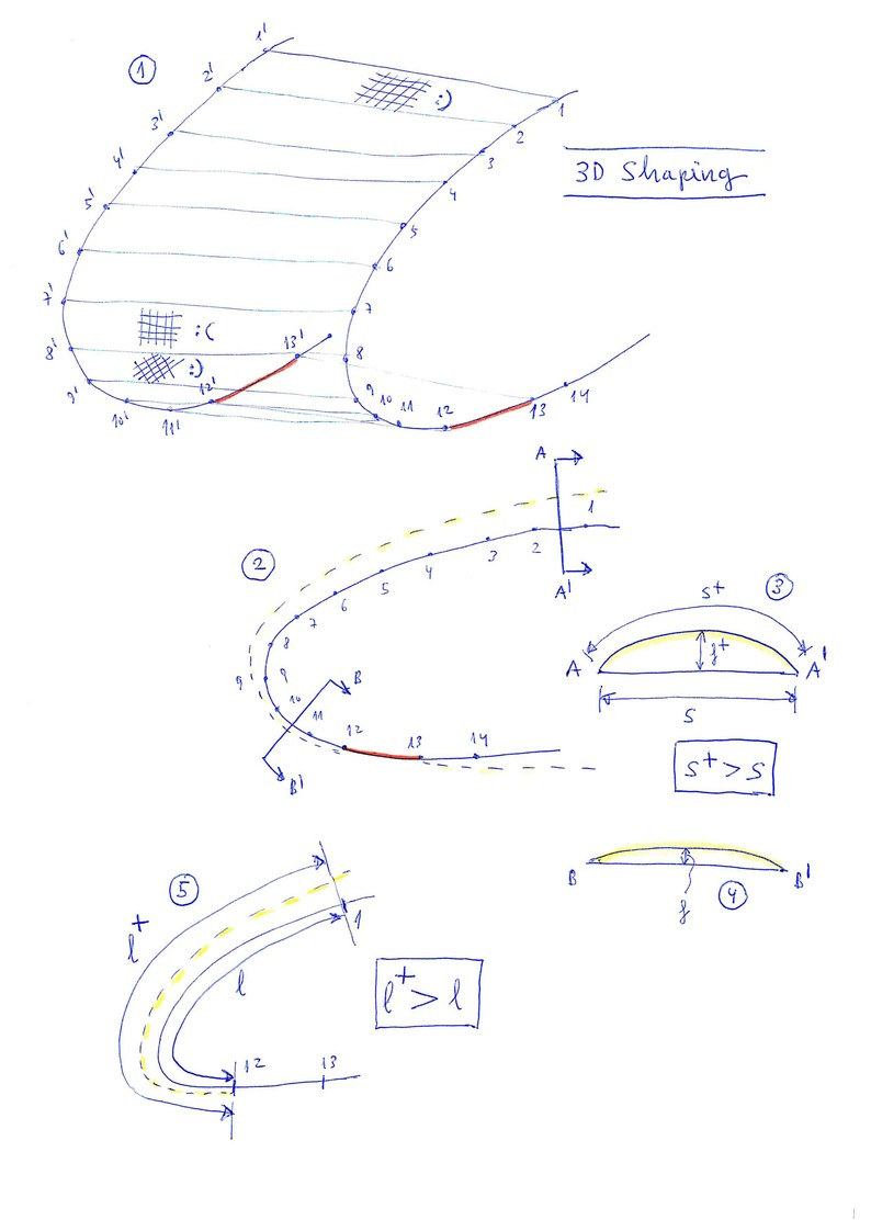
1. Leading edge model
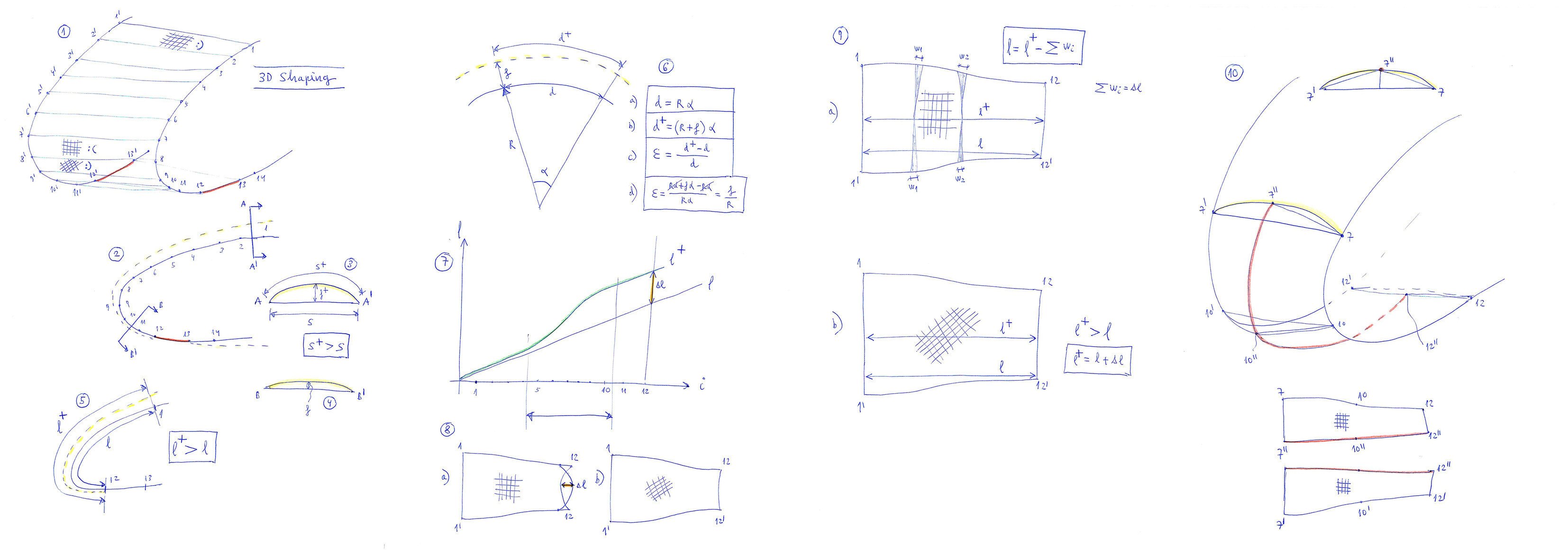
Consider the frontal part (nose) of a cell formed between two consecutive profiles. The model considers the left profile, composed by successive points 1,2,3,4,... linked by segments. And the right profile, consisting of corresponding points 1',2',3',4'... The surface of the nose is formed through the space quadrilateral 1-1'-2-2', and successives.
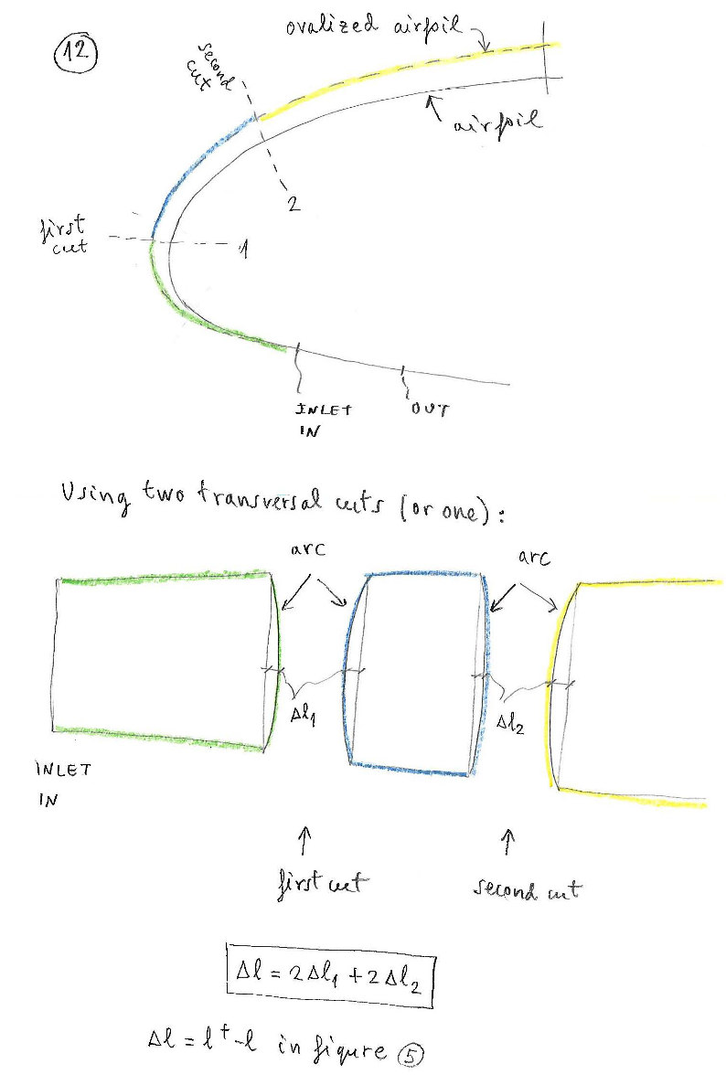
2. Ovalization
Consider a side view of the nose. Considering that the internal pressure of the wing is greater than the external, the cell adopts a cylindrical shape (ovalization). At the front of the wing, it is advisable to increase the tension of the fabric forcing less ovalization. The approximate profile of ovalization is marked in dashed yellow line.
3. 4. Sections
Sections 3 and 4
showing a section of the panel in two different points. It shows the first problem to solve in the formation of the 3D surface. The distance along the fabric (s+) is greater than the straight-line distance between corresponding points (s). This is easily solved by adding a little of fabric laterally.
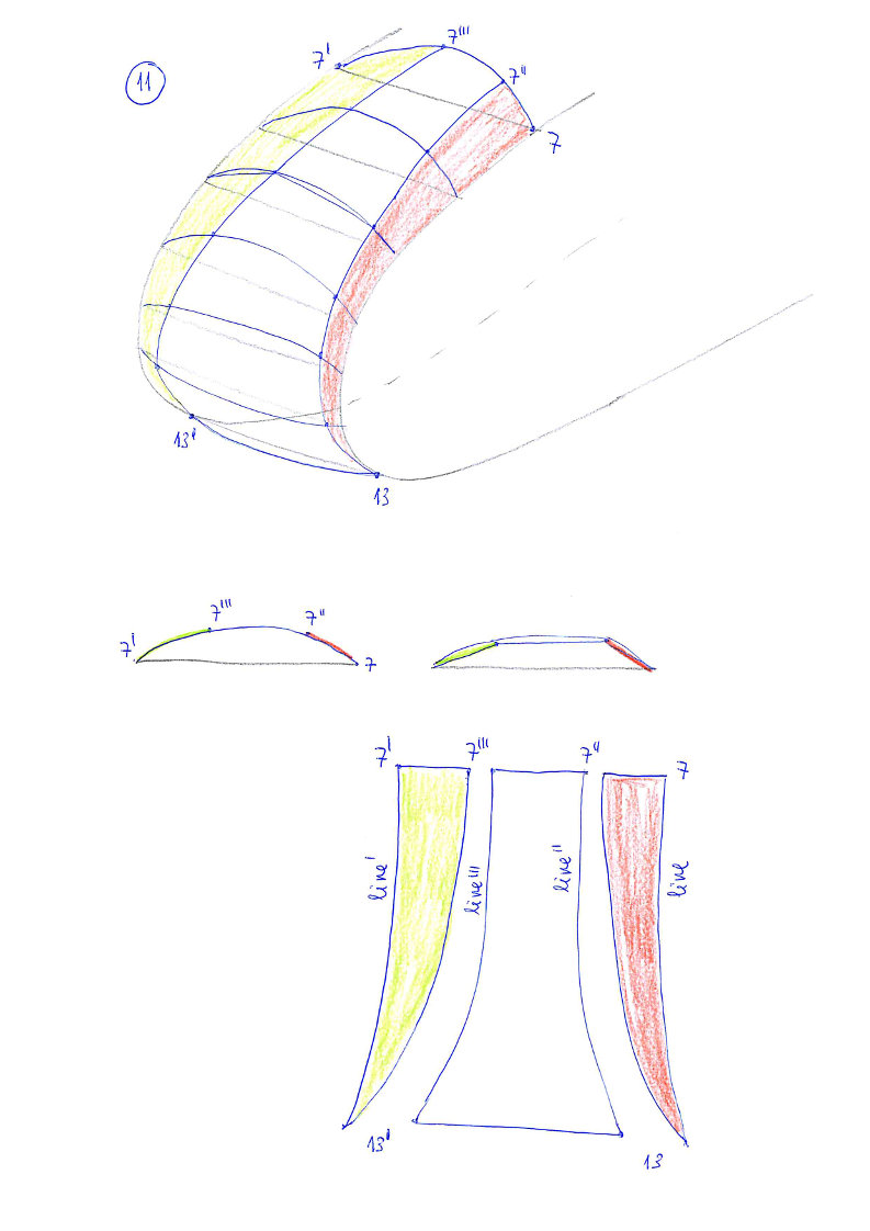
5. Length differences in the nose panel
If we look from the side view, we see the second problem. The length (l+) along the center of the ovalized panel (ovalitzat) is greater than the lateral length (l).
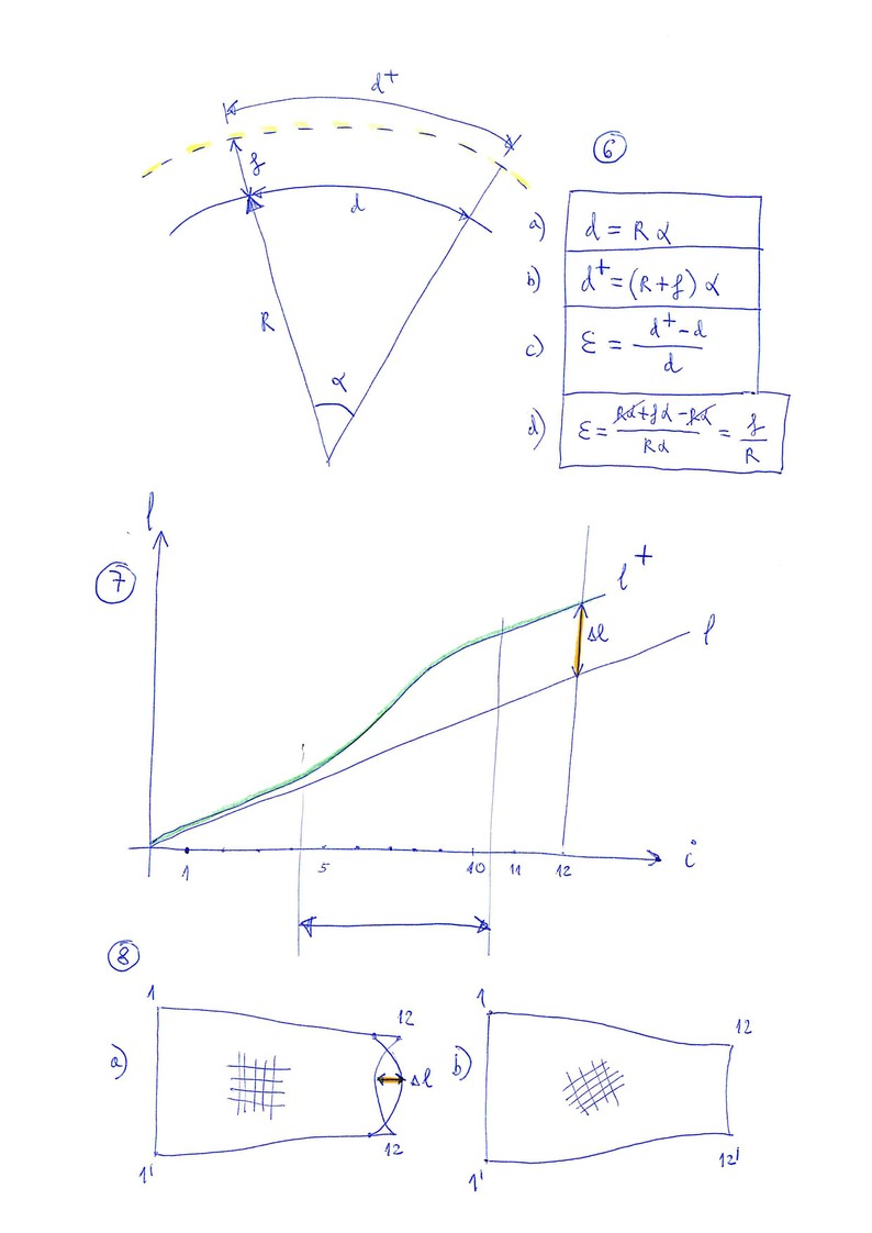
6. Deformation per unit
We deduce that the deformation per unit (epsilon) is directly proportional to the "arrow" (f) of the ovalization and inversely proportional to the radius (R) of curvature of the nose: Epsilon=f/R
7. Increments in length along nose
If we represent the accumulated length from the initial point of reference, we see a graph similar to the one represented. In the area of greatest curvature, is where the largest deformation will occur.
8. Problems in the panel
But the flat panel of ripstop fabric is not very deformable in the direction of the grid. So there will be problems in the final form (a figure).
Turning the grid of the panel 45 degrees, then the deformation required will be better adapted to the panel (b figure.
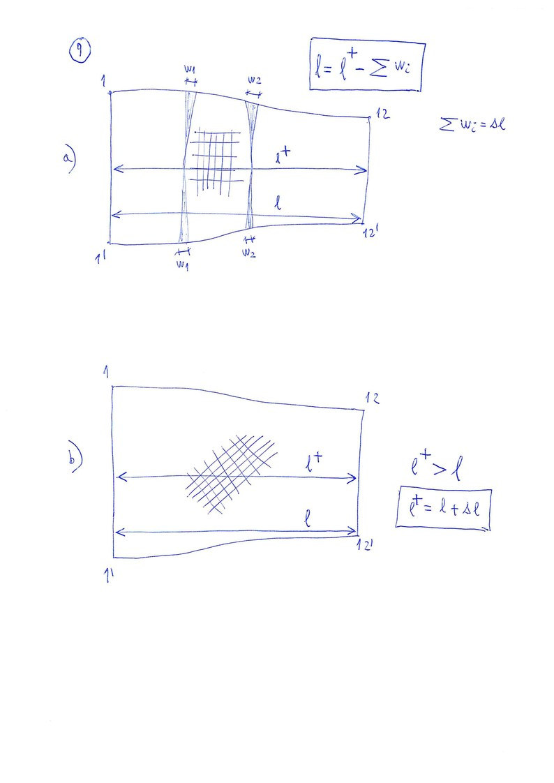
9. Details in the nose panel
Let's see in more detail. In the first case (a), since in the direction of the grid there is little distortion, the length of the panel reduces in lateral sides, forming small wrinkles (w). In the second case (b), the fabric is deformed in the center better to the required length. Naturally, to achieve this it is necessary to sew the nose panel with a separate piece of fabric, and properly oriented grid.