Changing the scale of a glider, from plans in DXF or DWG format, (CAD type) is easy.
The size of a wing, usually refers to its area in square meters (m2) or
square feet (ft2). To change the scale of the plans, either in 2D or
3D, just apply a linear scaling factor K. This factor is applied to the
three axes X, Y, and Z if necessary.
Find the linear scaling factor K is easy.
In the figure below:
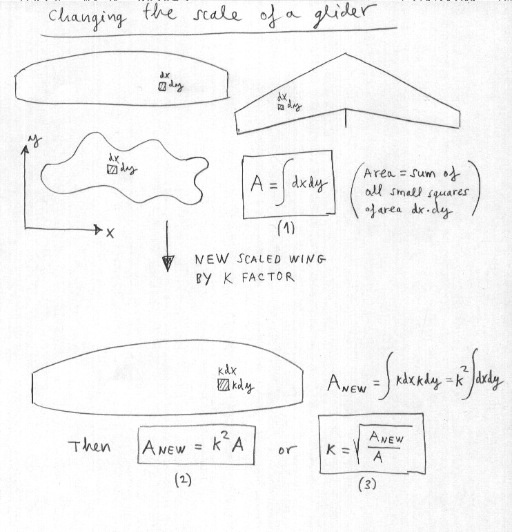
The area of a wing (
or any other plane figure) can be calculated as the sum of the areas of small squares that completely fill the inside.
If the squares are small, the numerical approximation is very good. For
example if we consider a square of size dx in the direction of the X
axis, and dy in the direction of the axis Y, the total area of the wing
is:
A = sum of all the squares of area dx·dy [formula 1]
Now, if you apply a scale factor K (K>1 for larger wing, ok K<1
for smaller size), then the squares change to a size k·dx on X and k·dY
in Y axis. Then, the new area of the wing is A_new= sum of all small
squares of area k·dx·k·dy i.e.
A_new= K^2 · A [formula 2] , or what is the same:
k=SQRT(A_new/A) [formula 3]
This is the linear scaling factor to apply to move from one wing from
the original area A, a new area A_new. Easier to do than explain!
Using this system, the plans of the wings published in this site in DXF format, can be scaled easily to build other larger or smaller sizes. Must take into account that the sewing edges also be scaled smaller or larger. The new lengths of the lines are obtained by multiplying the original length by the scale factor.